Бүтээгдэхүүний дэлгэрэнгүй тайлбар
PRODUCT DESCRIPTION
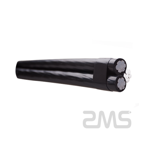
1. 0.6/1kV Overhead Cable
2. Aluminum Conductor
3. XLPE /PE Insulation
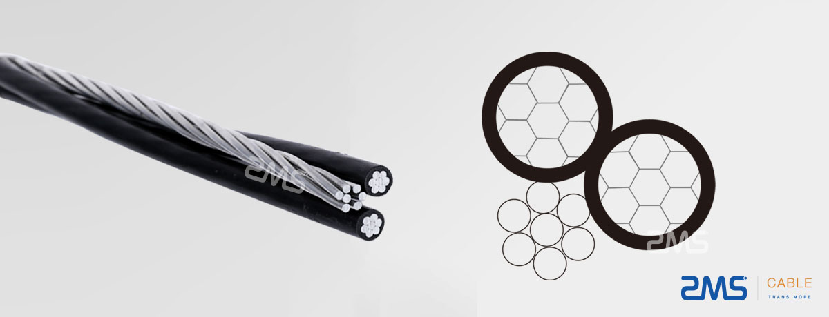
4. Phase Conductor+ Neutral Conductor
5. IEC ICEA NFC Standard
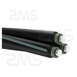
LV Aerial Bundled Conductor (ABC) Cables
APPLICATION OF TRIPELX ABC CABLE
Aerial Bundle Cable (ABC cable) is a very innovative concept for overhead powerdistribution as compared to the conventional bare conductor overhead cable
PROPERTY SYSTEM.
| Electrical Properties | |
|---|---|
| Rated Voltage 0.6/1kV | |
| Test Voltage | 4VeffkV |
| minimum laying Temperature | -20°C |
| operating Temperature | -40°C~ +90°C |
| maximum Short-circuit Temperature | 250°C |
| maximum Conductor Temperature | 80°C |
| minimum Bending radius | 18×OD |
It provides higher level of safety and reliability, lower power losses and ultimate system economy by reducing installation, maintenance and operative cost.
LV Aerial Bundle Cables are designed to supply 600/1000 volt aerial service for temporary service at construction sites, as a service drop (power pole to service entrance), as a secondary cable (pole to pole) or street lighting.
This over-head cable providesreinforced insulation acc. IEC 61140 and fulfill therefore Class II acc. IEC 61140.
It is not flame retardant. But this could be if requested change to a flame retardant cable.
STANDARD OF TRIPELX ABC CABLE
Basic design to BS 7870 / TNB Specification (IEC 60502) / HD 626 S1 / NFC 33-209 / AS/NZS 3560-1 standards
Construction Of Tripelx ABC Cable
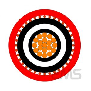
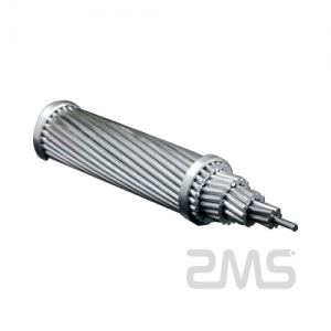
Conductor: Aluminium conductor, round stranded compressed (RM).
Insulation: XPLE compound, UV-resistant.
Core Identification: 1, 2 resp. 3 raised longitudinal ribs on the surface of the cores.
The surface of the neutral core should have at least 12 ribs for cross-sections up to 50 mm²
and a minimum of 16 ribs for cores above 50 mm². In the case of five core bundles the
surface of the protective core should be smooth.
CONSTRUCTION PARAMETERS OF TRIPELX ABC CABLE TNB SPECIFICATION (IEC 60502)
| number of cores xNominal cross Section | overall diameter | weight | Maxinum conductor Resistance | Minimun breaking Load | current Rating |
|---|---|---|---|---|---|
| No.xmm2 | mm | kg/km | Ω/Km | KN | A |
| 1×16+1×25 RM | 15.3 | 160 | 1,910 | 2,5 | 72 |
| 3×16+1×25 RM | 19 | 290 | 1,200 | 4,0 | 107 |
| 3×25+1×25 RM | 23.2 | 400 | 0,868 | 5,5 | 132 |
| 3×35+1×25 RM | 25.6 | 500 | 0,641 | 8,0 | 165 |
| 3×50+1×35 RM | 30 | 680 | 0,443 | 10,7 | 205 |
| 3×70+1×50 RM | 34.9 | 920 | 0,320 | 13,7 | 240 |
| 3×95+1×70 RM | 40.6 | 1270 | 0,253 | 18,6 | 290 |
| 3×120+1×70 RM | 44.1 | 1510 | 0,206 | 23,2 | 334 |
| 3×150+1×95 RM | 49.2 | 1870 | 0,164 | 28,7 | 389 |
| 3×185+1×120 RM | 54.9 | 2340 | 0,125 | 37,2 | 467 |
| 3×25+1×25+1×16 RM | 23.2 | 470 | 1,910 | 2,5 | 72 |
| 3×35+1×25+1×16 RM | 25.6 | 560 | 1,200 | 4,0 | 107 |
| 3×50+1×35+1×16 RM | 30 | 740 | 0,868 | 5,5 | 132 |
| 3×70+1×50+1×16 RM | 34.9 | 980 | 0,641 | 8,0 | 165 |
| 3×95+1×70+1×16 RM | 40.6 | 1330 | 0,443 | 10,7 | 205 |
| 3×120+1×70+1×16 RM | 44.1 | 1580 | 0,320 | 13,7 | 240 |
| 3×150+1×95+1×16 RM | 49.2 | 1940 | 0,206 | 23,2 | 334 |
| 3×185+1×120+1×16 RM | 54.9 | 2410 | 1,910 | 2,5 | 72 |


