

Бүтээгдэхүүний дэлгэрэнгүй тайлбар
APPLICATIONS:
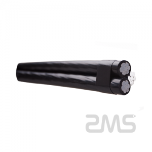
The cables are designed for distribution of electrical power with nominal voltage Uo/U 19/33KV and frequency 50Hz. It is used to transmit and distribute power in power transmission and distribution system of 33kV or lower. It is generally applied to the fields including power, construction, mines, metallurgy, petrochemical industry and communication in complete replace of oil immersed paper insulated power cable and in partial replace of PVC insulated power cable.
STANDARD:
BS 6622
BS 7835 (LSZH Version)
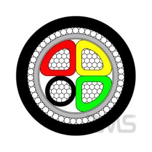
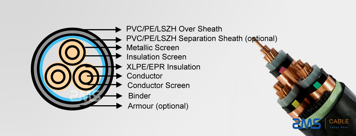
CONSTRUCTION:
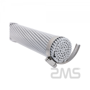
Conductor: Plain annealed copper or aluminium complying with IEC 60228/BS 6360. Copper
conductors shall be stranded and aluminium conductors shall be either solid or
stranded.
Conductor Screen: Extruded layer of semi-conducting cross-linkable compound is applied
over the conductor and shall cover the surface completely. The minimum thickness is 0.3mm
and the maximum resistivity shall not exceed 500 Ohm-m at 90°C.
Insulation: Insulation is of cross-linked polyethylene compound XLPE (GP8) conforming to
BS 7655-1.3 or EPR (GP7), conforming to BS 7655-1.2.
TABLE 1. INSULATION THICKNESS:
| Nom. Cross Section Area | Insulation Thickness at Nom. Voltage |
| 19/33KV(Um=36KV) | |
| mm² | mm |
| 70 – 185 | 8.0 |
| 240 | 8.0 |
| 300 | 8.0 |
| 400 | 8.0 |
| Above 500 | 8.0 |
Insulaton Screen: Extruded layer of semi-conducting cross-linkable compound is applied
over the insulation. The extruded semi-conducting layer shall consist of bonded or cold
strippable semi-conducting compound capable of removal for jointing or terminating. As an
option, a semi-conducting tape may be applied over the extruded semi-conducting layer as a
bedding for the metallic layer. The minimum thickness is 0.3 mm and the maximum resistivity
is 500 Ohm-m at 90°C. The screen is tightly fitted to the insulation to exclude all air voids and
can be easily hand stripped on site.
Inner Covering; Fillers: For cables with a collective metallic layer or cables with a metallic
layer over each individual cores with additional collective metallic layers, semi-conducting
inner covering and fillers shall be applied over the laid up cores. The inner covering is made
of non hygroscopic material, except if the cable is to be made longitudinally watertight. The
inner covering shall be extruded or lapped.
The approximate thickness of extruded inner coverings is given in Table 2:
TABLE 2. APPROXIMATE THICKNESS OF EXTRUDED INNER COVERINGS
| Ficititous Diameter over Laid Up Cores; | Approx. Thickness of Extruded Inner Covering; | |
| mm; | mm | |
| >; | <; | |
| – | 25 | 1.0 |
| 25 | 35 | 1.2 |
| 35 | 45 | 1.4 |
| 45 | 60 | 1.6 |
| 60 | 80 | 1.8 |
| 80 | – | 2.0 |
Metallic Layer: The metallic layer shall be applied over each core or applied as a collective
screen. The metallic screen shall consist of either copper tapes or a concentric layer of
copper wires or a combination of tapes and wires. The metallic layer provides an earth
fault current path, capable of withstanding fault current to earth of 1000A for one second at
maximum temperature 160°C. Copper wires are applied over the conducting water blocking
layer with a minimum diameter of 0.5mm. And over the copper wires, copper tape with
minimum thickness of 0.1mm can be applied helically with overlap.
Total cross section of copper wire screen is shown in table 3.
TABLE 3. MINIMUM TOTAL CROSS SECTION OF COPPER WIRE SCREEN; DC RESISTANCE OF THE SCREEN
| Nominal Cross-Section Area of Cable | Minimum Cross-Section of Copper Wire Screen Area | DC Resistance of the Copper Wire Screen |
| mm² | mm² | mm |
| up to;120 | 16 | 1.06 |
| 150-300 | 25 | 0.72 |
| 400-630 | 35 | 0.51 |
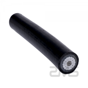
Separation Sheath (for armoured cable): The separation sheath comprises a layer of extruded PVC, PE or LSZH. The nominal thickness is calculated by 0.02Du + 0.6mm where Du is the fictitious diameter under the sheath in mm. The nominal separation sheath thickness
shall not be less than 1.2mm.
Armour (for armoured cable): The armour consists of galvanized steel wire applied over the
inner covering with diameter specified as in Table 4.
TABLE 4. ARMOUR WIRE DIAMETER
| Fictitiious Diameter under the Armour | Armour Wire Diameter | |
| mm | mm | |
| > | < | |
| – | 25 | 1.6 |
| 25 | 35 | 2.0 |
| 35 | 60 | 2.5 |
| 60 | – | 3.15 |
Over Sheath: Overall sheath comprises a layer of extruded either PVC type 9 conforming
to BS 7665-4.2 or MDPE type TS2 conforming to BS 7655-10.1; LSZH can be offered as an
option. The over sheath is normally black in colour. When a DC voltage test is to be performed on the over sheath, a semi-conducting layer such as graphite coating shall be applied over the surface of the extruded over sheath. The nominal over sheath thickness is calculated by 0.035D+1 where D is the diameter immediately under the over sheath in mm. For cables with the over sheath not applied over the armour, the nominal over sheath thickness shall not be less than 1.4mm. And for cables with over sheath applied over the armour, the nominal over sheath thickness shall not be less than 1.8mm.
PHYSICAL PROPERTIES:
Operating Temperature: up to 90°C
Temperature Range: -5°C ( PVC or LSZH sheath ); -20°C ( PE sheath )
Short Circuit Temperature: 250°C (short circuit duration up to 5 seconds)
Bending Radius: 12 x OD
DIMENSIONAL DATA:
| Nom. Cross- Section Area |
Nom. Insulation Thickness |
Copper Tape Screen Area |
Nom.Bedding Thickness |
Nom. Armour Wire Diameter |
Nom.Sheath Thickness |
Approx. Overall Diameter |
Approx. Weight | |
| CU | AL | |||||||
| mm² | mm | mm² | mm | mm | mm | mm | kg/km | |
| 50 | 8.0 | 6.7 | 1.8 | 3.15 | 3.4 | 79.0 | 10620 | 9680 |
| 70 | 8.0 | 7.1 | 1.8 | 3.15 | 3.5 | 82.5 | 11840 | 10440 |
| 95 | 8.0 | 7.5 | 1.9 | 3.15 | 3.6 | 86.4 | 13200 | 11350 |
| 120 | 8.0 | 7.9 | 2.0 | 3.15 | 3.7 | 89.9 | 14520 | 12190 |
| 150 | 8.0 | 8.2 | 2.0 | 3.15 | 3.8 | 93.6 | 16070 | 13280 |
| 185 | 8.0 | 8.6 | 2.1 | 3.15 | 3.9 | 97.3 | 17710 | 14090 |
| 240 | 8.0 | 9.2 | 2.2 | 3.15 | 4.1 | 103.2 | 20370 | 15460 |
| 300 | 8.0 | 9.7 | 2.3 | 3.15 | 4.3 | 108.2 | 22980 | 17210 |
| 400 | 8.0 | 10.3 | 2.4 | 3.15 | 4.5 | 116.8 | 27480 | 19450 |
ELECTRICAL DATA:
| Nom.Cross- Section Area |
DC Resistance CUAL |
AC Resistance CUAL |
ShortCircuit Rating of Conductor CUAL 1sec |
Capacitance | Charging Current |
Reactance | Inductance |
| mm² | µΩm | µΩ/m | kA | pF/m | mA/m | µΩm | nH/m |
| 25 | 727/1200 | 927/1538 | 3.6/2.3 | 176 | 0.48 | 132 | 410 |
| 35 | 524/868 | 668/1113 | 5.0/3.2 | 193 | 0.53 | 123 | 390 |
| 50 | 387/641 | 494/822 | 6.8/4.4 | 211 | 0.58 | 116 | 370 |
| 70 | 268/443 | 343/568 | 9.8/6.3 | 240 | 0.65 | 110 | 350 |
| 95 | 193/320 | 248/410 | 13.3/8.5 | 267 | 0.73 | 105 | 330 |
| 120 | 153/253 | 196/325 | 17.2/11.0 | 291 | 0.79 | 102 | 320 |
| 150 | 124/206 | 159/265 | 21.2/13.5 | 312 | 0.85 | 98 | 310 |
| 185 | 99.1/164 | 128/211 | 26.6/17.0 | 340 | 0.93 | 95 | 300 |
| 240 | 75.4/125 | 98/161 | 34.9/22.3 | 375 | 1 | 91 | 290 |
| 300 | 60.1/100 | 80/130 | 43.8/28.0 | 411 | 1.1 | 89 | 280 |
| 400 | 47.0/77.8 | 64/102 | 57.3/36.6 | 454 | 1.2 | 84 | 270 |